
Normalised Warping Function
Warping and Torsion
SCI P057 (Ref 1) provides an excellent reference for warping and torsion of beams. It contains useful formulas for standard I and channel sections. However, for non-standard sections, for example those built-up from a number of sections (like crane rail girders), it is difficult to obtain an analytical solution to the normalised warping function and warping statical moment . These functions are required to calculate the warping normal stress and the warping shear stress respectively. The functions are based on the geometry of the section, but vary at any point on the section.
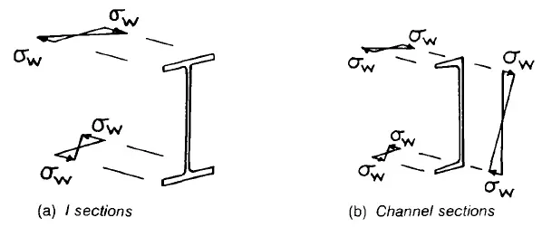
Warping Stresses
Normalised Warping Function for Non-Standard Sections
For non-standard sections, the complication integral formulas in Appendix A of SCI P057 are very hard to apply. This article suggests an alternative method using a simple finite element model under simple loading conditions to calculate the normalised warping function and warping statical moment .
The magnitude of the warping normal stress at any particular point ‘s’ in the cross section is given by:
Where
is the normalised warping function at the particular point ‘s’ in the cross section.
From this relationship we can construct a simple FE model where the warping normal stress, elastic modulus and second derivative of the angle of twist can be determined, leaving the unknown normalised warping function to be calculated. The normalised warping function is a function of the section, so after determining this from an FE model under simple loading it can now be used for more complicated loading.
Methodology
The section is created in ANSYS of an arbitrary length and meshed with a solid mesh. A torque (torsional moment) is applied to one end, with the other end fixed. The torque should be applied about the shear centre. This loading sets up a pure torsional warping stress state, i.e. the results are not muddied by axial loads or bending moments.
Displacements are output and processed in Excel to calculate the angle of twist. A typical plot of the angle vs. the distance along the member is shown in the figure below.
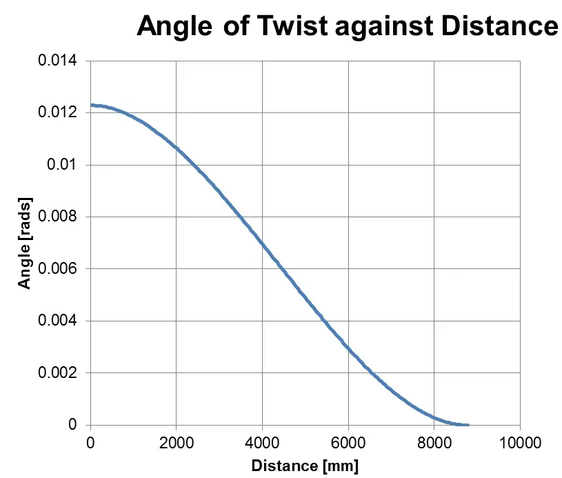
Angle of Twist vs. Distance Along the Member
Once the angle of twist with distance along the member is calculated this data can be curve fitted with a 3rd order polynomial. Excel can helpfully provide the polynomial coefficients which then means we can differentiate the angle function twice to get . As this is just an equation, we can helpfully plot this as a User Defined Function in ANSYS, as shown below.
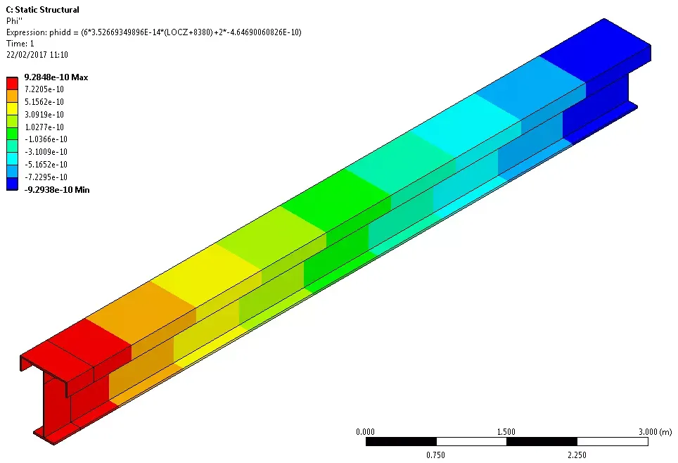
Second Derivative of Angle of Twist
From this, the normalised warping function can be calculated as:
is just the SZ stress in this case as there are no other stresses in the axial direction except this normal warping stress. We can also plot the normalised warping function as a User Defined Function in ANSYS, as shown below.
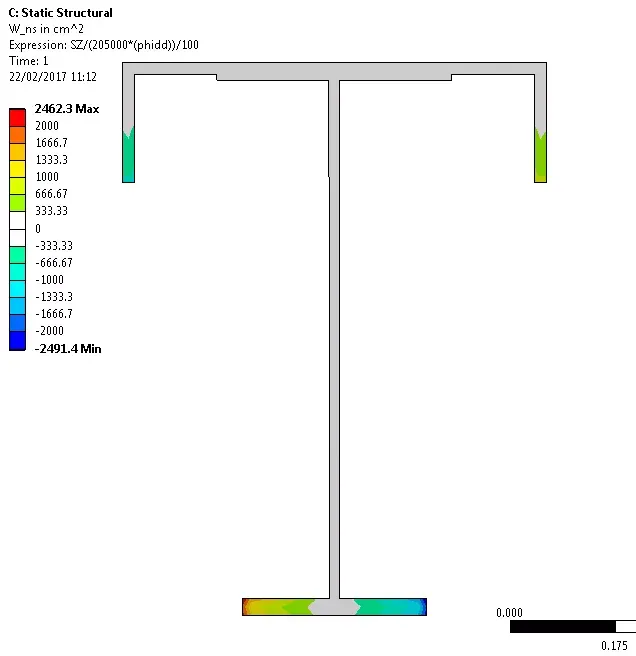
Normalised Warping Function
Similarly we can take the third derivative of the angle of twist, and from this the warping statical moment can be calculated. These are properties of the geometry of the section, but varying with position on the section. Now they have been derived from a simple load case, the normalised warping function and warping statical moment can be used for combined torsion and bending load cases using SCI P057.
References
- SCI P057, Design of Members Subject to Combined Bending and Torsion, The Steel Construction Institute