
Bending Moment and Shear Force Diagrams for Solid Bodies in ANSYS Workbench
Bending Moment and Shear Force Diagrams for Solid Bodies in ANSYS Workbench
There are times when you have a solid model, but want to plot bending moment or shear force diagrams, either as a sanity check compared to a simple hand calculation or for assessment where the code calls for forces and moments rather than stresses. For beam element models extracting and plot bending moment and shear force diagrams is easy, but for solid bodies there is no quick way.
A work-around that I had been using for a while is to use the Force Probe in Workbench scoped to a Surface, which is great for getting the forces or moments at a single section, but when I wanted a bending moment diagram I would have to manually move the Surface, recalculate the sections forces, write them down in Excel, move the Surface… etc… all very tedious and time-consuming.
Getting Bending Moment and Shear Force Diagrams in ANSYS Workbench Easily
That lead me to look at writing a macro or script to automate this process. I didn’t fancy delving into the Javascripting of Mechanical, which would have enabled me to move the Surface programmatically. Instead I opted to write a Code Snippet using APDL, with the method of extracting section forces and moments being the integration of stresses using the surface operations available in APDL. Note that a limitation of this is that it only works for 3D solid continuum elements, no beams or shells. You wouldn’t need this method for beam elements anyway as by default you can easily extract forces and moments, but it would be useful to be able to apply this to shell elements, and the Force Probe method in Mechanical does allow shell elements, so possibly there is a way to do this.
The method of integrating the section stresses to calculate shear forces and bending moments is detailed in the following article:
I’d also like to recognise the useful help in rotating coordinate systems and using the ANSYS APDL surface operations that is detailed here:
Code Snippet for ANSYS Workbench
Here is the final Code Snippet for ANSYS Workbench. Insert a Code Snippet object under the Solution branch, and paste the contents below in to the editor. Then you need to do the following to set up the script:
- Create a Coordinate System at the starting point for where you want to calculate the section forces. This must have a manually set ID corresponding to ARG1 in the Code Snippet. I use 12. The origin of the Coordinate System is important as that is where moments will be calculated about. Also, the local Z axis of the Coordinate System must align with the axis of the body you want to calculate the results for, with positive Z pointing along the body towards the end. You can create a Coordinate System in Mechanical directly, but this will only be available for use in the post processing if you create the Coordinate System before running the analysis. If you already have results and don’t want to rerun, then instead you can create the Coordinate System inside the Code Snippet, as shown in the example below.
- Create a Named Selection called
CM_Section_Forcesand scoped to the body that you are interested in. As above, if you have already solved the model then any newly-created Named Selections won’t be available, so as a work-around you can define them directly in the Code Snippet, as I have done below. - Populate ARG1 to 3 of the Code Snippet as follows:
- ARG1 – coordinate system (number) at the starting point, with it’s local Z axis in the direction that you want to create the bending moment diagram
- ARG2 – distance, measured from the local coordinate system (in ARG1) over which you want to calculate the bending moment
- ARG3 – number of increments to split the distance into to calculate results. More increments will take longer to process.
- Make sure
Save MAPDL dbis set to Yes in Analysis Settings
And the actual Code Snippet to create bending moment and shear force diagrams of solid bodies in ANSYS Workbench is pasted below, but if you have issues copying it, download it below.
! =======================================
! USER INPUT
! =======================================
! - define a Named Selection called CM_Section_Forces scoped to the body of interest
! - define a Local Coordinate System at the starting point, with it's local Z axis in the direction
!   that you want to create the bending moment diagram. Moment are calculated about this origin, which moves along the body with each increment.

! ARG1 - coordinate system (number) at the starting point, with it's local Z axis in the direction that you want to create the bending moment diagram
! ARG2 - distance, measured from the local coordinate system (in ARG1) over which you want to calculate the bending moment
! ARG3 - number of increments to split the distance into to calculate results

! Note: a text file of results will automatically open when the calculation is complete, but you'll need to close this to complete the update

! =======================================
! AUTHOR AND DATE
! =======================================
! Nick Stevens
! September 2016
! https://nickjstevens.netlify.com/
! Thanks to SimuTech Group, in particular this article: http://www.simutechgroup.com/FEA/fea-tips-tricks-stress-linearization.html
! Stress resultants article: https://en.wikipedia.org/wiki/Stress_resultants

! =======================================
! INITIALISE MACRO
! =======================================
resume

!########################################################################
! If you've already solved the model, then any subsequently created coordinate
! systems or named selections won't be available, so instead you can create
! them here as a fudge to avoid resolving the model
!########################################################################
! create coordinate system - the number (12 in this case) is populated in ARG1
LOCAL, 12, 0, 675, 30, 80, , 90
! create named selection, which needs to be called CM_Section_Forces
esel,s,mat,,11,13
cm,CM_Section_Forces,elem
allsel
!########################################################################

/show,png
/GFILE,500 !image size
/CMAP,_TEMPCMAP_,CMP,,SAVE
/RGB,INDEX,100,100,100,0
/RGB,INDEX,0,0,0,15

increment=ARG2/(ARG3-1)

! dimension results arrays
*dim,asurf_Mx,table,ARG3
*dim,asurf_My,table,ARG3
*dim,asurf_Fz,table,ARG3
*dim,asurf_Vx,table,ARG3
*dim,asurf_Vy,table,ARG3
*dim,asurf_Tz,table,ARG3
*dim,asurf_Dist,table,ARG3


/post1
set,last

Local_CS=ARG1                    !coordinate system
cmsel,s,CM_Section_Forces        ! select elements of body/bodies of interest
nsle,s,active ! select nodes

WPCSYS,,Local_CS                 ! place working plane at origin of coord sys ARG1
/CPLANE,1                        ! cutting plane is working plane
WPSTYL,,,,,,0,2,1                ! cartesian WP with triad shown

! =======================================
! START LOOP
! =======================================

*do,i,1,ARG3
  ! get origin and orientation of "Local_CS" coordinate system
  *GET,x_orig,CDSY,Local_CS,LOC,X ! get the origin
  *GET,y_orig,CDSY,Local_CS,LOC,Y
  *GET,z_orig,CDSY,Local_CS,LOC,Z
  *GET,THXY,CDSY,Local_CS,ANG,XY  ! get the orientation
  *GET,THYZ,CDSY,Local_CS,ANG,YZ
  *GET,THZX,CDSY,Local_CS,ANG,ZX

  ! create surface
  SUCR,mysurf,CPLANE,3
  SUSEL,S,mysurf

  ! get info needed to rotate results in to local coordinate system
  *get,thxy,CDSY,4,ANG,XY    ! First rotation, about the Global Z axis, that put working plane where it is
  *get,thyz,CDSY,4,ANG,YZ    ! Second rotation, about the new X axis, that put working plane where it is
  *get,thzx,CDSY,4,ANG,ZX    ! Third rotation, about the newest Y axis, that put working plane where it is
  *get,origx,CDSY,4,LOC,X    ! location of the origin of the working plane, in Global Cartesian
  *get,origy,CDSY,4,LOC,Y    ! location of the origin of the working plane, in Global Cartesian
  *get,origz,CDSY,4,LOC,Z    ! location of the origin of the working plane, in Global Cartesian

  ! Form cosine and sin terms as used in a rotation matrix
  *afun,deg
  c1=cos(thxy)               ! Cosine of THXY, first rotation about Global Z
  s1=sin(thxy)
  c2=cos(thyz)               ! Cosine of THYZ, second rotation about the new X
  s2=sin(thyz)
  c3=cos(thzx)               ! Cosine of THZX, third rotation about the newest Y
  s3=sin(thzx)
  *afun,rad                  ! return to default radians

  ! Form the 3x3 rotation matrix
  R11=c3*c1-s3*s2*s1
  R12=c3*s1+s3*s2*c1
  R13=-s3*c2
  R21=-c2*s1
  R22=c2*c1
  R23=s2
  R31=s3*c1+c3*s2*s1
  R32=s3*s1-c3*s2*c1
  R33=c3*c2

  SUCALC,MyZero,DA,ZERO,,,,0.0 ! a dummy surface result (of zeroes) that is used in calculations later

  SUCALC,GCXX,GCX,SUB,MyZero, , ,-origx
  SUCALC,GCYY,GCY,SUB,MyZero, , ,-origy
  SUCALC,GCZZ,GCZ,SUB,MyZero, , ,-origz

  SUCALC,sr11,DA,ZERO,,,,r11      ! rotation matrix terms
  SUCALC,sr12,DA,ZERO,,,,r12
  SUCALC,sr13,DA,ZERO,,,,r13
  SUCALC,sr21,DA,ZERO,,,,r21
  SUCALC,sr22,DA,ZERO,,,,r22
  SUCALC,sr23,DA,ZERO,,,,r23
  SUCALC,sr31,DA,ZERO,,,,r31
  SUCALC,sr32,DA,ZERO,,,,r32
  SUCALC,sr33,DA,ZERO,,,,r33

  ! Form working plane coordinates
  ! First do X
  SUCALC,WPX1,sr11,MULT,GCXX      ! R11*X
  SUCALC,WPX2,sr12,MULT,GCYY      ! R12*Y
  SUCALC,WPX3,sr13,MULT,GCZZ      ! R13*Z
  SUCALC,WPX,WPX1,ADD,WPX2
  SUCALC,WPX,WPX,ADD,WPX3         ! Form X ON WORKING PLANE = R11*X+R12*Y+R13*Z

  ! Then do Y
  SUCALC,WPY1,sr21,MULT,GCXX      ! R21*X
  SUCALC,WPY2,sr22,MULT,GCYY      ! R22*Y
  SUCALC,WPY3,sr23,MULT,GCZZ      ! R23*Z
  SUCALC,WPY,WPY1,ADD,WPY2
  SUCALC,WPY,WPY,ADD,WPY3         ! Form Y ON WORKING PLANE = R21*X+R22*Y+R23*Z

  ! Then do Z (for checking - all points should be on the same plane)
  SUCALC,WPZ1,sr31,MULT,GCXX      ! R31*X
  SUCALC,WPZ2,sr32,MULT,GCYY      ! R32*Y
  SUCALC,WPZ3,sr33,MULT,GCZZ      ! R33*Z
  SUCALC,WPZ,WPZ1,ADD,WPZ2
  SUCALC,WPZ,WPZ,ADD,WPZ3         ! Form Z ON WORKING PLANE = R31*X+R32*Y+R33*Z

  RSYS,ARG1 !results coordinate system using local CS

  ! Mapping onto the surface
  SUMAP,szz,S,Z               ! map SZ (axial) onto the surface
  SUMAP,sxz,S,XZ              ! map shear stress SXY
  SUMAP,syz,S,YZ              ! map shear stress SYZ

  ! Form products in anticipation of calculating stress resultants
  sucalc,szz_y,szz,MULT,WPY
  sucalc,szz_x,szz,MULT,WPX
  sucalc,s_tors1,syz,MULT,WPX
  sucalc,s_tors2,sxz,MULT,WPY
  SUCALC,s_tors,s_tors1,SUB,s_tors2

  ! Form integrals. This produces stress resultants about the origin of the local coordinate system
  sueval,Mx,szz_y,INTG
  sueval,My,szz_x,INTG
  sueval,Fz,szz,INTG
  sueval,Vx,sxz,INTG
  sueval,Vy,syz,INTG
  sueval,Tz,s_tors,INTG

  ! Finally map results to output arrays
  asurf_Mx(i)=Mx
  asurf_My(i)=-My !negative sign required for My - see Wikipedia on Stress Resultants
  asurf_Fz(i)=Fz
  asurf_Vx(i)=Vx
  asurf_Vy(i)=Vy
  asurf_Tz(i)=Tz
  asurf_Dist(i)=(i-1)*increment

  ! Offset the working plane and local coordinate system ready to go round the loop again
  WPOFFS,,,increment
  CSWPLAN,ARG1,0

*enddo
! =======================================
! END LOOP
! =======================================

! =======================================
! WRITE AND OPEN RESULTS
! =======================================

*cfopen,Section_Results,txt                               ! creates file called Section_Results.txt, which will be in Solver Files Directory
*vwrite,'Dist','Vx','Vy','Fz','Mx','My','Tz'
(7(2X,A16))
*vwrite,asurf_Dist(1),asurf_Vx(1),asurf_Vy(1),asurf_Fz(1),asurf_Mx(1),asurf_My(1),asurf_Tz(1)
(7(2X,F16.2))
*cfclos

/title,Vx against Distance
/GCOLUMN, 1, Vx
/AXLAB, X, Distance
/AXLAB, Y, Shear Force Vx
*VPLOT, asurf_Dist, asurf_Vx

/title,Vy against Distance
/GCOLUMN, 1, Vy
/AXLAB, X, Distance
/AXLAB, Y, Shear Force Vy
*VPLOT, asurf_Dist, asurf_Vy

/title,Fz against Distance
/GCOLUMN, 1, Fz
/AXLAB, X, Distance
/AXLAB, Y, Axial Force Fz
*VPLOT, asurf_Dist, asurf_Fz

/title,Mx against Distance
/GCOLUMN, 1, Mx
/AXLAB, X, Distance
/AXLAB, Y, Moment Mx
*VPLOT, asurf_Dist, asurf_Mx

/title,My against Distance
/GCOLUMN, 1, My
/AXLAB, X, Distance
/AXLAB, Y, Moment My
*VPLOT, asurf_Dist, asurf_My

/title,Tz against Distance
/GCOLUMN, 1, Tz
/AXLAB, X, Distance
/AXLAB, Y, Torsion Moment Tz
*VPLOT, asurf_Dist, asurf_Tz

/VIEW,1,1,1,1
/TRIA,LBOT
/PSYMB,CS,1
/title,Orientation System and Surface
WPSTYL,,,,,,0,0,1                ! cartesian WP with triad shown
nplot
!supl,mysurf,WPZ,1

! opens the created results file in Notepad:
/sys,notepad Section_Results.txt

/CMAP,_TEMPCMAP_,CMP
/show,close
rsys,0
csys,0
allsel
Results
A test case is considered below, where the shear forces and bending moment diagrams are required for a shear pin:
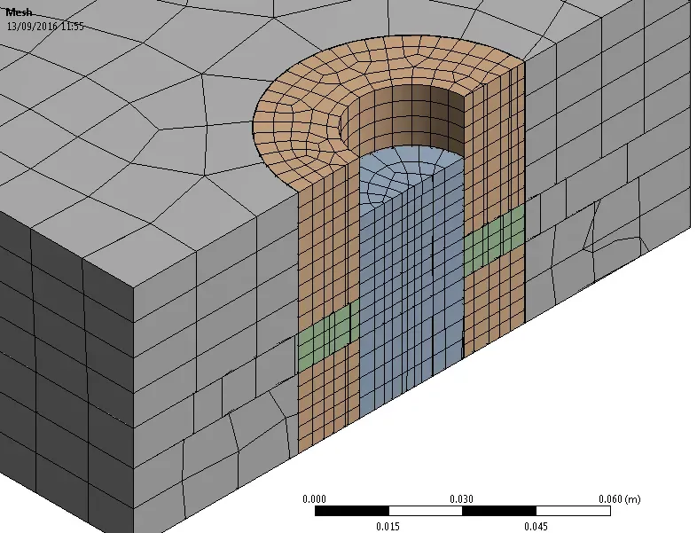
Shear Pin
The Code Snippet is inserted and the input arguments entered:

Code Snippet Input Arguments
A number of plots are generated, as well as a text file with the full results:
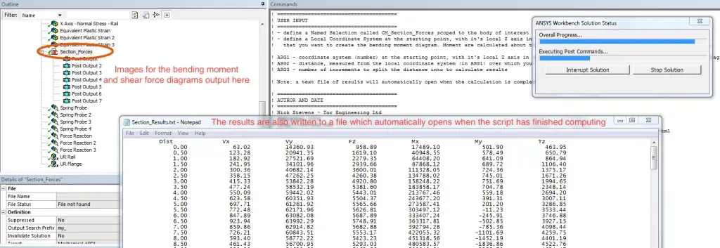
Bending Moment and Shear Force Diagram Output
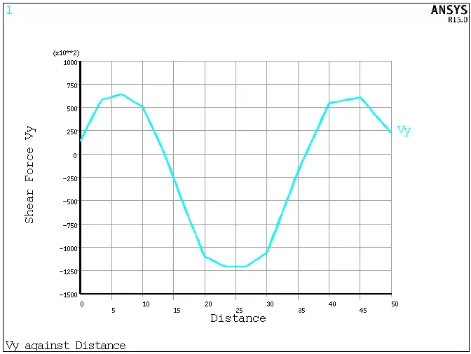
Shear Force Diagram Output Plot
And that’s it! Might be useful. A few things to note: it’s still important that mesh refinement is done to ensure that the results have converged. Also, this is only applicable for small displacement problems, as the section plane does not rotate and remains fixed wherever it started.
Future Work
I would love to develop this further by encapsulating it as an ACT Extension. I’ve never done this before, so it’s all new to me, and if anyone would like to collaborate and work on this together then that would be great.
Hope you find it useful!